Matrix Operations: Rotation and Translation
Let’s dive into some of the actual math required to make a 3D game work. This time we will look at some matrix algebra that enables us to do rotation and translation of our 3D objects.
This is the fourth post in a series about recreating the Stunt Car Racer game for modern platforms. You can find the previous posts by looking the Stunt Car Racer tag. A very quick recap: We have some existing C++ code which uses the Direct3D API to render the graphics, but since that is Windows-specific, we want to convert it to OpenGL. This involves understanding some of the matrix math going on, since it works slightly differently in Direct3D and OpenGL - the order of matrix multiplications are switched around, and some of the coordinate systems are a bit different.
In the previous post we quickly skipped past the matrix math required to do rotation, translation, and perspective. Let’s dive into that now, since it’s really interesting. In this post we will do rotation and translation, and then we will look at perspective in the next post.
Reading time: 10 minutes
The Vertex Shader
As you may remember, our vertex shader - the function that transforms our initial 3D points to 2D points that can be rendered on our 2D screens - looks something like this:
attribute vec3 vPosition;
uniform mat4 projectionMatrix;
uniform mat4 viewMatrix;
uniform mat4 worldMatrix;

void main() {
  gl_Position = vPosition * worldMatrix * viewMatrix * projectionMatrix;
}
This is running as part of the OpenGL rendering pipeline, to which we supply an array of 3D points.
These points will eventually be mapped to the 2D space of our monitor. OpenGL tears apart our array of 3D points
and feeds them to individual calls to the vertex shader through the vPosition variable. We also supply three
matrices: A projection matrix, a view matrix, and a world matrix.
You may have noticed that the one variable that changes on each invocation of the vertex shader is prefixed
with attribute, while the variables that stay constant during the rendering of our array of 3D points are
prefixed with uniform. We won’t get into those specifics in this post, but it’s something you need to keep
in mind when writing your own vertex shader.
Why supply three matrices? This is a convention in 3D graphics libraries.
- The world matrix will transform points from “model space” to wherever in the world and in whatever rotation your model is placed.
- The view matrix will transform points from “world space” to “view space”, which means the points will be moved to adjust for the camera position and rotation. After applying this matrix, the camera will be at the (0, 0, 0) point and looking in a certain, well-defined direction.
- The projection matrix ensures that points far away from the camera are drawn closer together than points close to the camera, so it looks like 3D.
I’ll provide some examples in a moment. We could just multiply all these matrices before invoking the OpenGL pipeline and have a simpler vertex shader, but I want to stay true to what the current C++ Stunt Car Racer code is doing. Besides, there are some benefits to this way of doing it - for example, the view matrix will only change once on each new frame we render, while the projection matrix will only change when the player resizes the window.
You may be wondering why we are using 4x4 matrices (the mat4 type in the shader code above) when we want to
render 3D objects, not 4D objects. This will become apparent soon.
Dial Down on Dimensions
But before we proceed, allow me to simplify all the math involved. Instead of taking 3D objects, putting them in a 3D world, and rendering them on a 2D screen, let’s take 2D objects, put them in a 2D world, and render them on a 1D screen. (I know, not a lot of blockbuster games transfer nicely to a 1D display…) This allows us to more easily show - in this blog post, on your 2D screen - what is going on. And luckily, the linear algebra we use as a foundation scales easily from 2 to 3 dimensions. Just trust me 😅
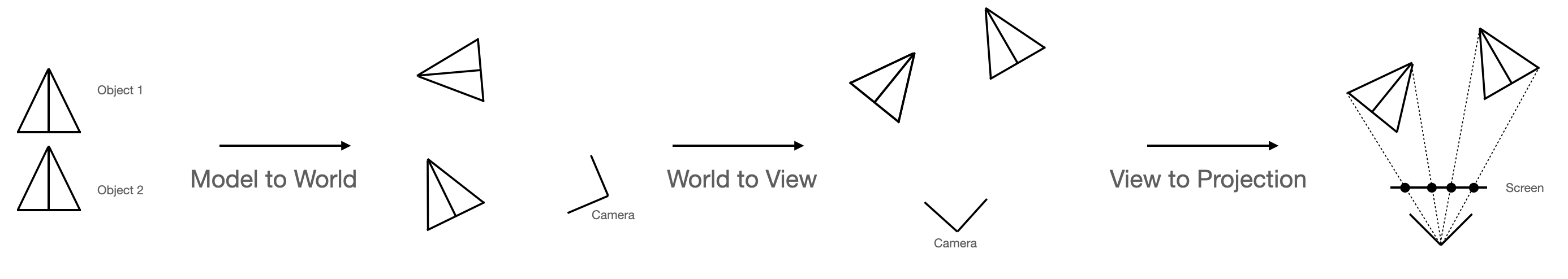
If that’s OK with you, then consider this example: We have two objects (paper planes?) that we first move to their “world positions”. Then we move the world around so that the camera is at a certain place and looking upwards, and finally we “flatten” the world so we can draw it on our 1-dimensional screen.
Refresher: Multiply a Vector and a Matrix
In the rest of this article, we’ll need to multiply vectors and matrices. You can look up the rules, but I will spare you the trouble. Multiplying a two-dimensional vector and a 2x2 matrix results in a two-dimensional vector, and it goes like this:
Similarly, multiplying a three-dimensional vector with a 3x3 matrix goes like this:
(Sorry, you may need to scroll the formula in order to see all of it…)
You can also multiply matrices with matrices, but you’ll have to look that up by yourself. (I’m using MathML here, and it’s just too painful to write this up.)
Rotation
Let’s say we have a point
that we want to rotate at angle ß around
so we end up at point
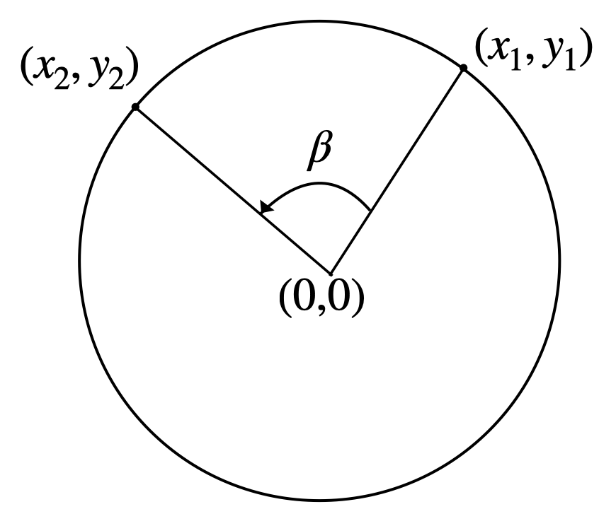
How do we do that? You can look it up and arrive at this formula:
You may ask what this has to do with matrix multiplication. It just turns out that this is exactly the same as writing it like this:
Just check with the rules for multiplying a vector and a matrix above. In other words: By multiplying our point with the matrix
we get our rotation, so this matrix is our “rotation matrix”.
Translation
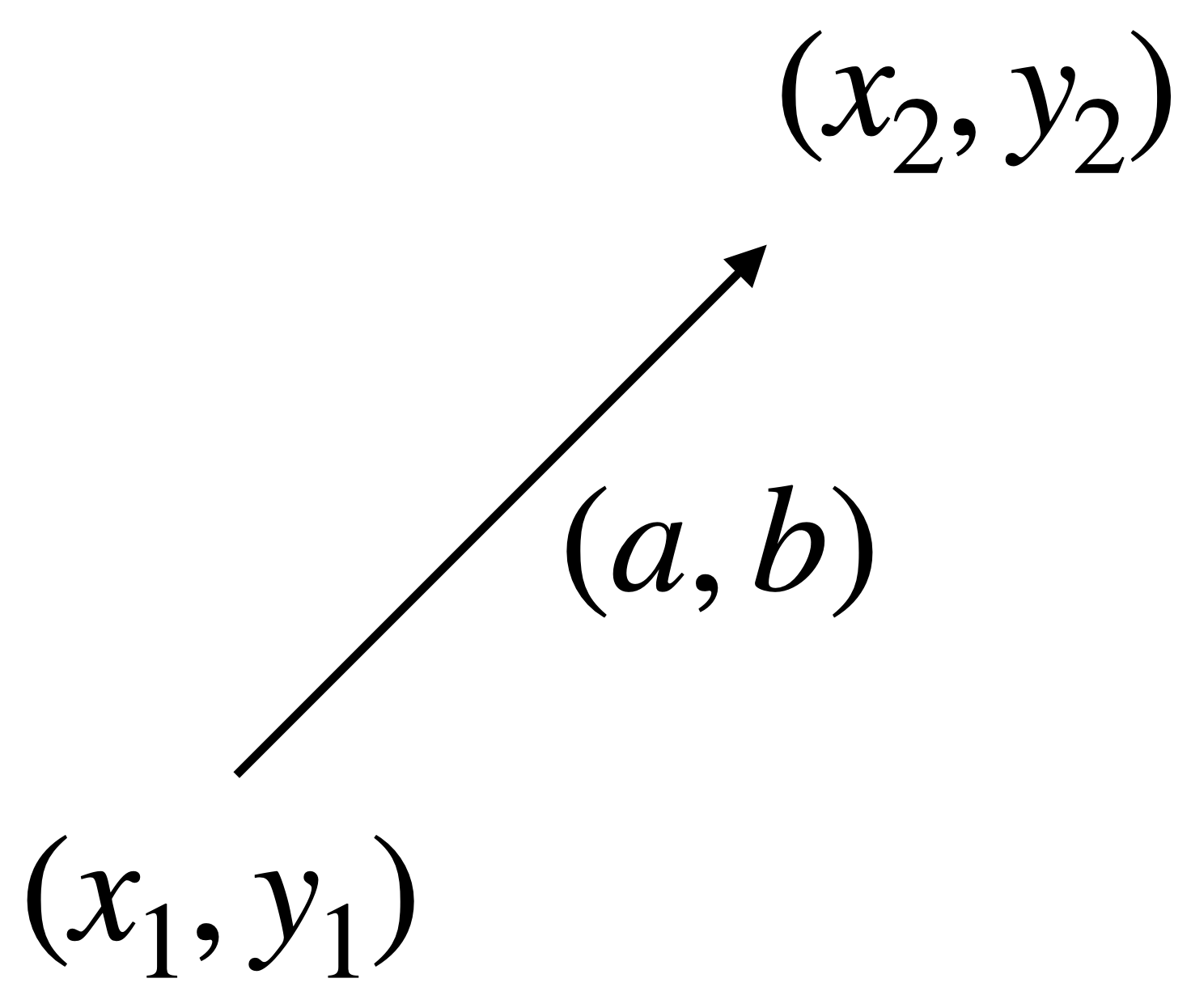
One down! We now know how to rotate points. But we also need to know how to use matrix algebra to move points in certain directions. Say we have a point
that we want to move in a direction and distance defined by the vector
so we end up at point
Our first reaction is of course to see if there is any way we can create a 2x2 matrix such that
But that’s just not possible! No matter what you try, an x, y, or a multiplication gets in the way of just adding a constant to the initial coordinates. What to do?
Let’s Add a Dimension!
The solution may not seem very straightforward, but what if we add another dimension to our 2D vector and start using 3D vectors and 3x3 matrices? If we always put a 1 at the third coordinate in our vector, then we have a well-defined constant that our matrix multiplication can make use of:
Try to do the math yourself and see if you arrive at the same result.
This is nice! We just add a third component, always set it to 1, and when multiplying our vector with our translation matrix, we get a new vector with the third component set to 1, which means we can keep multiplying translation matrices, and it will keep working nicely. That’s a nice property of matrix multiplication: It is easy to compose. So if you want to translate first in one direction, then another direction, and then a third direction, you can create translation matrices for each of these translations, multiply them all together, and the result will be one “translation matrix to rule them all” which represents the combination of all the translations.
So this explains why, in our original 3D example, we need to use 4D vectors and 4x4 matrices.
Revisiting Rotation
But we’re not done yet, because our rotation matrix is still 2x2. To be able to multiply all of our matrices without considering whether it’s a rotation matrix, a translation matrix, or any combination, we need a 3x3 rotation matrix with the same properties as our 3x3 translation matrix.
Luckily, the solution is very straightforward:
This will make sure that we preserve the 1 in our 3rd vector coordinate, while resulting in the same results for x and y. Try to do the math if you don’t believe me.
Generalizing From 2D to 3D
All of the above works on 2D models, a 2D world, and a 1D screen. As promised in the beginning of this post, it really does work almost exactly the same way if we use 3D models, a 3D world, and a 2D screen.
Translation is pretty straightforward - basically just add another component to your vector, but still keep the last component set to 1. The same principle goes for the matrix.
Rotation is a tiny bit more complex, but not much. When you rotate, what you normally will do is decide whether to rotate around the X, Y, or Z axis, so instead of one “rotation matrix”, you will need to construct one for each of the three dimensions. Again I will leave this exercise to you.
Getting it Right Ain’t Easy
Now that we know what’s going on, it should be easy to get it all right. But even with the help of GitHub Copilot, my first attempt didn’t work out quite the way it should:
(There are other things wrong with this capture, but we’ll get back to that in the next post.)
After fidding with sin, cos, adding random -s etc., it eventually worked:
Adding some Perspective
We still need to go through the last step, which is “flattening” our 2D world into the one-dimensional screen (or rather, projecting our 3D world in Stunt Car Racer to your 2D computer screen). For this, we need to apply another trick. But that’ll have to wait for the next blog post.